
Almost ALL the late GM Alternator Information you could need!!
ALTERNATOR INFORMATION. So let's get this ironed out now. I see so many questions about alternators, and honestly, I see a LOT of wrong answers. I'm not the most informed on the situation, but I will share all the data I have to help some of you guys out. The LS engine came with many different alternators, but there are only really 2 different versions that make wiring different. (3 if you count the early Holden/Pontiac stuff. I have added information for these below) For the sake of being lazy, I'm going to refer to them as Early Version and Late Version.
Early Version LS alternators were commonly the CS230D, AD230, and AD244 series. These were Delco made units. The CS230D was what you would find on a stock 4th gen Camaro. The AD230 and AD244 were commonly found on the trucks. The AD230 was ~105a and the AD244 was ~130a. They both had the same mounting points, but the 244 was physically bigger than the 230. All these alternators have the oval, 4-pin Metri Pack 150 connector on the built-in regulator.


The AD244 is larger, moving the pulley further away from the standard center point of the AD230. A longer belt will be needed. GM calls for 20mm difference, which is around 1 inch.

This 4 pin regulator is easy to use. Some of them will not have ALL the pins in the receptacle, and this is fine. We only really need one pin for aftermarket use. So if you look close at the regulator receptacle, they are labeled S, F, L, and P. Your plug may be labeled different though. It might be a tan or black connector, and will be labeled A,B,C,D

S - this is the Sense circuit, like the old alternators that had one wire from the connector running directly to the B+ stud. The regulator has a built-in Sense circuit, so unless you want to get fancy, this isn't needed. But it was used to CHECK the voltage being hooked to this wire. It could be hooked somewhere inside the cab of the vehicle, to a main power source. This would help the alternator up the voltage to overcome voltage-drop in the system. Again, this is NOT needed for aftermarket use.
F - this is the Field Duty Cycle. This is a signal, produced by the alternator, and in factory applications, it was reported to the ECM or the GBCM for a few reasons. This could be used to produce a diagnostic code if the alternator had stopped charging. It also controlled the dash light, IF the light was not used for the Exciter circuit itself. When LED's were used in dashes, this was the way to control "Charge Light" This is not needed for aftermarket use.
L - THIS is the "Exciter" wire. The L means "light" which refers to an indicator light, that is called a 'dummy light' or 'generator light' pretty often. THIS is the MAIN control for the alternator, and we will go into great depth on this in the next paragraph.
P - this is a Pulse created by the stator of the alternator. The only use this ever got was to create a Tachometer signal for applications that did not have any means of crank location, OR it was used as an "engine on" signal for certain upgraded Brake systems. (you know those trucks with the vacuum assist motor on the brake booster? Yeah, that thing relies on an "engine on" signal) This is NOT needed for any aftermarket use.
So the L terminal is all that is needed to excite, or "turn on" the alternator. A small amount of amperage and voltage is applied here to excite, or magnetize the rotor. This allows the alternator to produce voltage when spinning. A full battery voltage/amperage here will destroy the unit. So one factory method was to pass an ignition circuit thru a light bulb, in series, to this terminal. So the voltage had the resistance of the bulb to lower it once the power was applied to the rotor. If the alternator failed to make voltage, this circuit was then LOWER voltage than the ignition circuit passing through the light bulb, so it caused the light to illuminate. This only works with incandescent bulbs. An LED does NOT have enough resistance to achieve the need goal.
But now days, we don't like to run a big dummy light in the dash, so we instead replace the light bulb with a resistor. The resistor is doing the EXACT same thing as the bulb, but we just don't have a visual aid if it fails. NOW, this is not a 5v circuit like everyone says. If you put a multi-meter on the circuit, with bulb or resistor in line, you will NOT see a drop in voltage. You will only see this if the connector is also hooked to the alternator. A resistor is a CURRENT LIMITING DEVICE, not a voltage limiting device. A single resistor will never have a large voltage drop.
So now we know to put a resistor inline to an ignition on power source. The most common resistor used for this is 470 ohm. Not 470 kohm, as this is a hugely different value. You can get away with a bit more resistance, such as 500-600ohm and be safe. Resistors are also categorized in WATTS. I prefer something near 1 watt for this application. Heat is the number one killer for a resistor, and heat can actually change the resistance of said resistor, without you even knowing it. A higher watt resistor will handle heat better. I use a KOA Speer #MOS1CT528R471J resistor in all my applications. They are high heat tolerant, small, and rated at 1 watt.
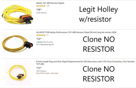
You can buy a pre-terminated pigtail from lots of venders. I see a lot of "clones" of the alternator pigtail out there, that DO NOT have the resistor in them. If you hook this up, without a bulb or resistor, you will fry the alternator in a few hours of driving. DON'T DO IT. Buy from a trusted source.
I know some of you prefer SELF EXCITING (SE) alternators. And these units can be converted to so Self Exciting regulator, BUT there are also some things to be noted on this. You won't be able to buy a SE unit from the parts store. You would have to have it converted as well. And, the way a SE regulator works, is it stores just a bit of magnetism in the rotor, to keep it able to charge. Now if that unit sets for long enough, this magnetism is lost, and now you have a no-charge situation. This requires you to get a small wire, and apply voltage to the exciter terminal for just a second, to re-apply the magnetism. So while the SE units are nice and easy to use, they still have some compromises.
NO OTHER wiring is needed on these early version alternators to get them to charge, other than your normal battery cable.
Later Version LS and LT alternators were altered for new factory features. They replaced the Delco units with Bosch units. They started around 05 in the Full Size vehicles and are found on almost every GM engine in production now. They came in many different forms. At first, the DR44 was a direct replacement for the AD244. They looked identical, and even came with the 4 pin regulator. These alternators were so close to an AD244, that they are still commonly called an AD unit, though they are no longer a Delco alternator. The exact same method as showed above, will work fine with these alternators. The Bosch units will be labeled DR44 or DR44G

Now that we got those oddball 4 pin Bosch units out of the way, we can focus on the 2 pin Variable Voltage alternators. They came with a variable voltage regulator, which only has a 2 pin connection. This regulator is capable of completely shutting the alternator off, or charging as high as 16v. This was to save fuel mileage during low power consumption, or command higher charge capabilities in high draw situations. But we like shit to go fast and don't commonly care to save a half MPG here and there. So we just need to have an alternator that works. So lots of people (and even big name companies) still think the resistor trick works, but guess what, it does not. All these "adapter harnesses" are NOTHING but a waste of money!!! There are a ton of harnesses out there that are "4 to 2" pin adapters and other stuff, but they wont change the charge voltage from the fail-safe amount.


The signal that controls the alternator is a proprietary PWM signal that is outlined by GM. So if the alternator doesn't see this signal, it just resorts to fail-safe mode, which is somewhere around 13.6v. Now you might be fine with this and not have an issue. But I like to see at least 14.5v from my alternator. This allows fuel pumps and other devices to perform at optimal levels, and allow the battery to charge to its full level. Rear mounted batteries are especially susceptible to problems since there can be as much a 1 volt drop in long cables, causing the battery to only see 12ish volts. Not really even charging the cells of the battery. Any of the above adapters will NOT change how it charges. It will do the same if it is plugged up or not.
On the GMT800 trucks, there was a separate computer that controlled the 2 pin alternator. This was the GBCM, Generator Battery Control Module. It was built into the the negative battery clamp. It measured load, and talked to multiple modules via the serial data network. It was actually a pretty sophisticated little setup. On newer vehicles, the calculations were done in the PCM, and only an amperage clamp was present on the battery cable. But it still had a method of producing the signal to control the alternator.

The 2 pins on the alternator are just F and L.
The F is Field Duty Cycle, just like the F terminal on the Early Version alternators. Its not needed.
But the L terminal is the PWM signal to control it. This is needed to control any usable charge from the alternator. It is a 5 volt, 128hZ signal, outlined in every GM manual that came with a vehicle that had 2 pin Bosch alternator. Altering the duty cycle will alter the voltage output of the alternator. Achieving that correct signal is not just easy-peasy. Here are just a few of the common 2 pin Bosch alternators.


I previously released a module for Tick Performance known as the TPALT44C. This was a stand-alone controller for the 2 pin Bosch alternators. We sold a ton of these!! These unit sets the alternator to charge at 14.4-14.6 volts. So there was no need to throw those alternators out. Some of these units are ~200 amps and have awesome lifespan to them. Custom voltage units could also may be ordered. BUT now that I have left Tick, we have the opportunity to redesign these modules and make them better. The new SMI-ALT44C, FOUND HERE will be able to control all the 2 pin alternators to the end user's selected voltage. They will now be programmable, along with being smaller, and if you change your setup down the road, we will do reprograms for a super cheap cost.

You will also notice that some of the connectors look different for the 2 pin units. There are some that are SHORUDED and some that are NON-SHROUDED. Just for clarity, ALL the alternators will take the non-shrouded connector, but not all of them will fit the shrouded style.

BUT WAIT, there is a 3rd version of alternator that was used on early Holden/Pontiac vehicles. So GTO's and G8's come with a Mitsubishi 3-phase alternator. This unit was COMPLETELY different than any of the Delco or Bosch alternators I have spoke of above, but they do share some similarities on the method to turn them on. The early units used a HUGE 2 pin connector. This is a Yazaki 7223-6224-40 connector, shown below.

This unit needs the resistor on the L terminal, just like the Early version LS unit, BUT this alternator does NOT have an internal Sense circuit. So you MUST connect the S terminal to the 12v of the car. This can be chosen by you. You can hook it directly to the 12v lug on the alternator, but this isn't the best. Connecting it near a main connection post used to power devices, or even directly to the battery is optimal. This lets the unit overcome some of the voltage drop in long runs of wires.

NOW, these units swapped to the smaller 2 pin PWM regulator around 2006. It was the same alternator, and its obvious that the small connector has a HUGE space, where it used to be the Larger Yazaki version. Pictures shown. This alternator needs the stand-alone module talked about above.
Here are the 2 alternators. Its easy to see the difference


We found a suspicious Google review from Andres Hernandez
GatherUp has a proven track record of removing fake and policy-breaking reviews. We’ll challenge this one with Google and stand behind the result with a 60-day 100% satisfaction guarantee. Trusted by 18,000+ businesses.
Book here: https://gatherup.chilipiper.com/router/meeting-review-defense
Is this store active?
Hi I am working on a 2005 Chevrolet Colorado it has a 2.8 L 4 cylinder engine. It has a AD 230 alternator with the wide 4 pin connector but only three pins. The wire harness has only 2 wires coming out. The dash light goes out after starting the engine but after about 1 minute the light comes back on and never goes back out. The voltage stays at 14.5 to 14,6 at the battery and alternator output post. I am stumped. Tried a new exciter plug same problem.
Well I have 98 vortex motor in stude and l terminal to choke wire is going me about 12.8 volts so far still figuring it out and , now friend has ls in Custoemr car with 2 plug wire oval top of plug flat bottom . I told L brown wire to key on output but now I see we should add a resister to its feed in-line ? Why is this alternator plug not shown in all your gm ls alternator that’s so weird ?
Outstanding, Im working on a 1979 FJ45 2H diesel, alternators about the only component I cant get working, its an ACD 334-2470A im on my third one. The guy who built and modified this 1979 Landcruiser got everything right except the charging circuit. The original Denso Alt had a long shaft thru the back of it that drove a Vac pump for the brakes. He removed the VR and OEM alt, went with this ACD alternator that fits well in stock brackets. Im waiting on a resistor to try to excite the alternator to get it too charge. Hope having put 12vdc on the field wire did not fry it (following other internet wiring diagrams).Thanks for this helpful bit of info.